It follows then that implement geometry should provide the opportunity to obtain an appropriate view of the crop. This is easily achieved for front mounted implements and for rear mounted implements which are substantially wider than the tractor.
However, smaller rear mounted implements need special consideration. For example, it might be appropriate to set frames back to provide a window through which crop rows can be viewed.
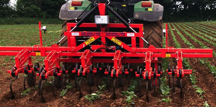
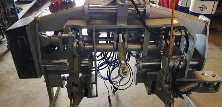
Cultivator frame set back to create a window through which the camera can view
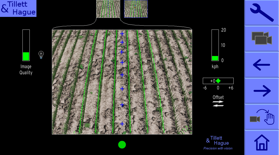
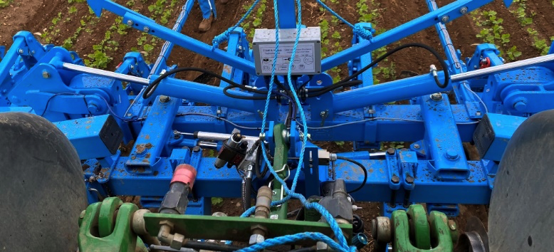
Where a single camera view is insufficient extra cameras can be fitted to provide more guidance data.
Two cameras following a single row each to make the best of a difficult situation
The vision system’s controller acts to laterally position camera(s), and anything mounted on the same frame, with respect to the crop rows in track. The camera must therefore be mounted rigidly on the moving part of the frame.
It is desirable to provide a means of independently adjusting camera height and lateral position without changing orientation. This allows each parameter to be changed in isolation.
For most applications we recommend mounting the camera relatively high, typically 1.6m above ground level looking down at about 40 degrees to the vertical. A good match between the systems digital template and the real crop rows is vital for good tracking. A higher camera makes that match less sensitive to height variation due to uneven ground or variation in crop height. However, there are circumstances e.g. crops with thin narrow stems at early growth stages, when the clearest view is gained by looking at an oblique angle viewing stems side on, requiring a relatively low camera height and a shallow camera angle.
It is therefore desirable to accommodate a range of camera mounting options if flexibility is important.
Steering mechanisms
Side shifting
Most inter-row vision guidance systems are used in conjunction with rear mounted side shifting headstocks. They provide a robust and effective positioning method entirely appropriate for most situations. From a vision guidance perspective, it makes little difference if side shifting motion is achieved using parallel arms or roller slide bearings. Both are acceptable.
Rear side shifting hitch with sliding mechanism
Rear side shifting hitch with parallel arm mechanism
Disk steering
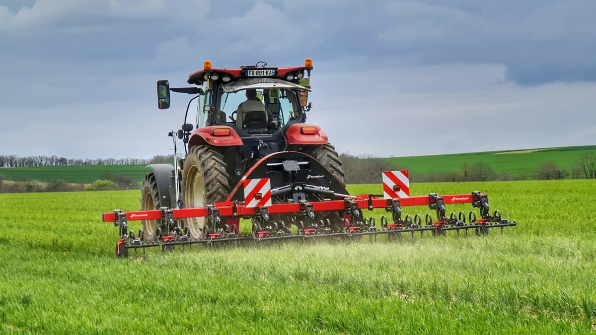
Front mount implements offer a good camera view but if ground engaging parts are difficult to move laterally then side shifting will impose equal and opposite lateral loads on the tractor. This does not normally cause a problem with rear mounted implements as the load is applied just behind the rear axle and will tend to steer the tractor in the same direction as the implement. However, a front mounted implement will apply load some distance ahead of the rear axle pushing the tractor and implement in opposite directions. This makes driving difficult and compromises accuracy. One solution is to mount the implement on a free shifting frame allowing the implement to float laterally with respect to the tractor and to use steered ground engaging wheels to guide the implement laterally.
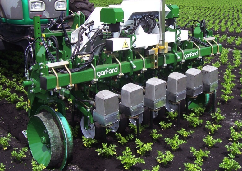
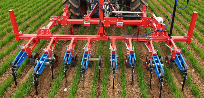
Disc steered front mounted implement with free shift slide
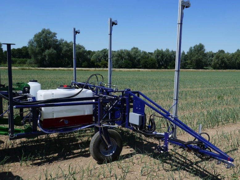
Steered wheels guide our own design of experimental spot sprayer mounted on a parallelogram floating frame
In our experience disc steering is slightly more accurate than side shifting.
Towed implements
It is also possible to use vision guidance to steer towed implements by side shifting the point at which the tow bar is hitched to the tractor. This technique works particularly well where the implement has strong directional stability e.g., from disc cultivators, as the lateral correction comes from pointing the implement in the direction you want it to travel. Whilst potentially accurate this geometry will be slow to correct lateral error if the tow bar is long and will not be accurate following curved crop rows. Towed implements are not common in Western Europe as they require large headlands.
DynaTrac
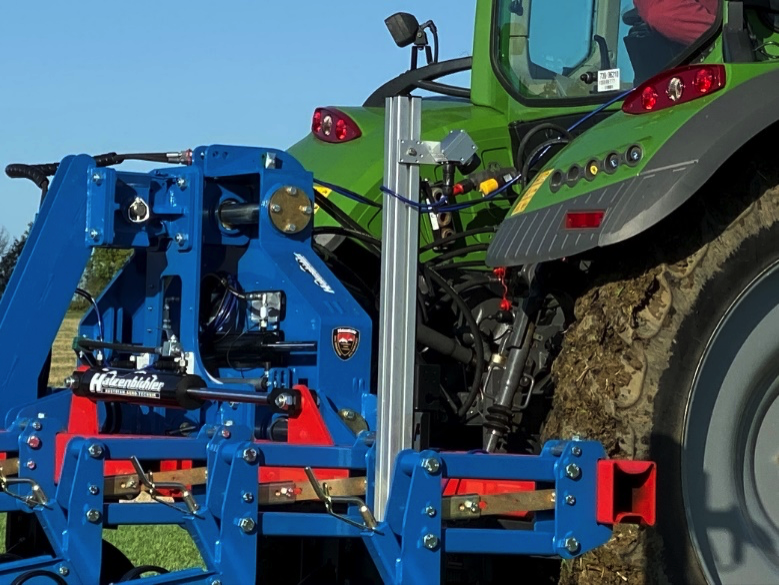
An interesting compromise is DynaTrac from LaForge. This mechanism, which we believe to be patented, side shifts a compressed second three-point linkage mounted on the tractor’s standard fixed linkage. Side shifting this second three-point linkage also side shifts its virtual hitch point and has a similar effect to side shifting a tow bar hitch point. With the DynaTrac lower link arms free to sway a directionally stable implement will tend to fall in line behind the virtual hitch point. It contrasts with a side shift in that the more directionally stable the implement the better it is likely to perform. If DynaTrac lower link arms are locked and unable to sway then it behaves like a conventional side shift.
LaForge “DynaTrac” which side shifts a virtual hitch point
NB
Please note that it is not advisable to use steered wheels to guide an implement mounted on a standard tractor three-point linkage with slack check chains or links. Whilst this arrangement does leave the implement free to move laterally it does so by rotating about the linkages virtual hitch point which will be fixed central to the tractor and a short distance ahead of the rear axle. Therefore, as the steered wheels push the implement in one direction it is being rotated in the opposite direction due to the geometry of the linkage. Our experience is that this conflict results in unsatisfactory performance. For similar reasons guiding a towed implement from a fixed hitch point by disc steering alone is likely to be unsatisfactory.
For a more comprehensive version of these design notes including choice of sensors and how to deal with more advanced applications such as within-row weeding and spot spraying please contact: nick.tillett@thtechnology.co.uk